Install the Slide Switches
Cow Pi mk1e: Arduino Nano form factor, SPI communication
In this section, you will install the “slide” switches that toggle between their two positions, holding their position until toggled again. We will wire them such that when a switch is toggled to the left, it will produce a 0, and when it is toggled to the right, it will produce a 1. Fig. 30 shows a diagram of the wiring for the slide switches.
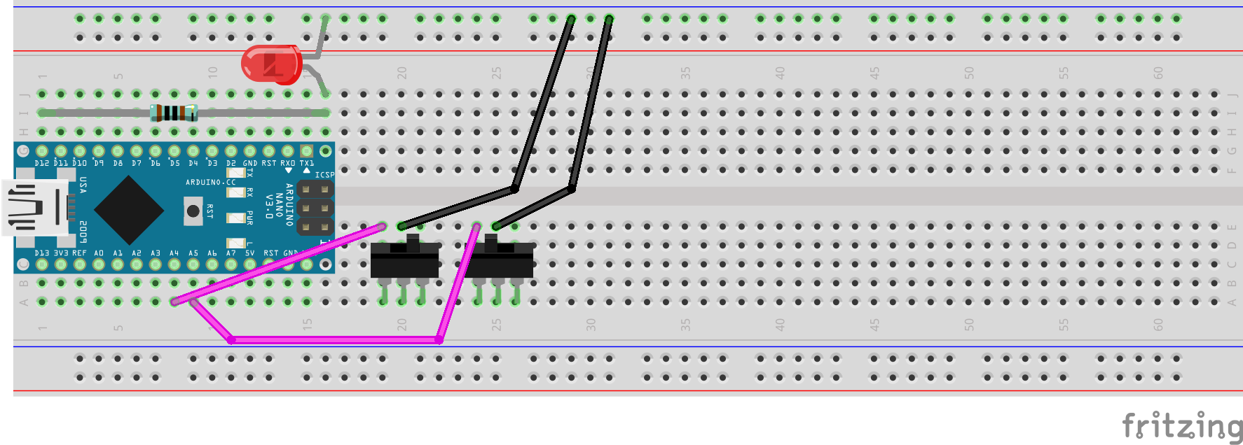
Fig. 30 Diagram of wiring associated with toggle switch input.
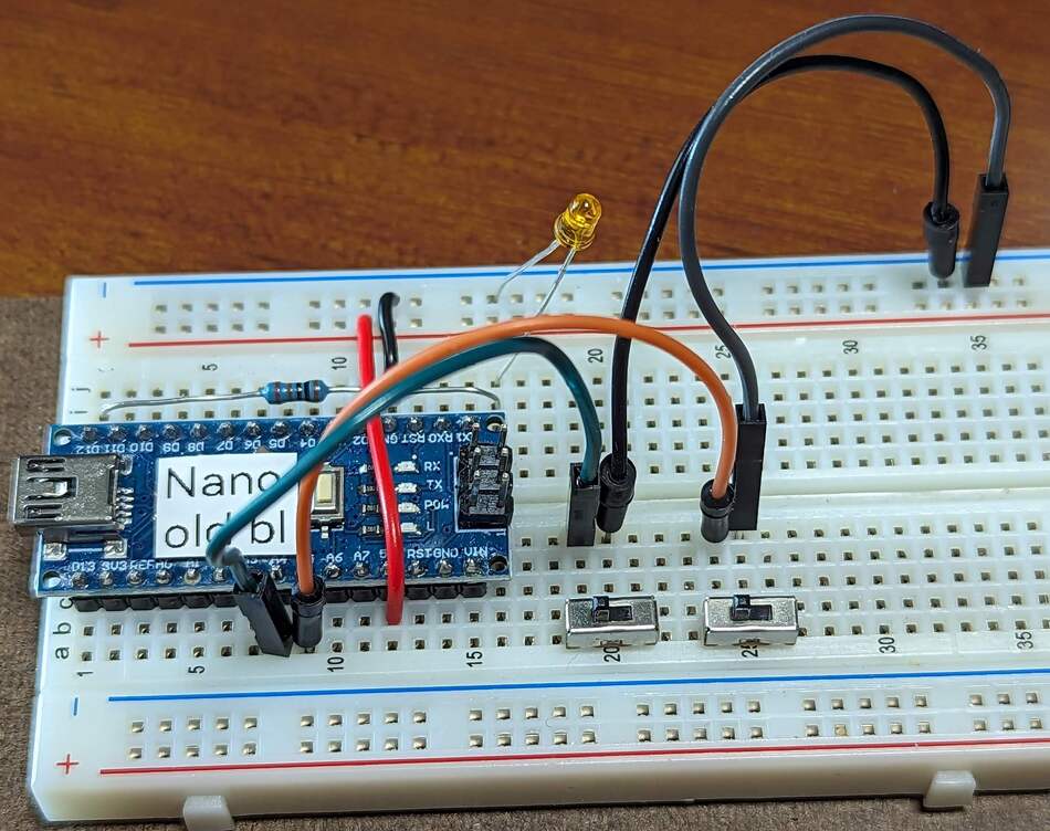
Fig. 31 The slide switches, each with the center pin grounded, the left pin connected to the Arduino Nano, and the right pin floating.
Important
Before proceeding further, disconnect the USB cable from the Arduino Nano.
- :[ ]:
Insert one slider switch into contact points a19-a21.
- :[ ]:
Place the other slider switch into contact points a24-a24.
For the two wires that will connect the switches to the Arduino Nano, you can use 10cm jumpers (especially if that is all that you have); however, if you use 20cm jumpers, then when you Install the Matrix Keypad a couple of pages after this one, we will show how to keep some wires away from the controls.
- :[ ]:
Peel off one wire from the male-to-male rainbow cable and use it to connect contact point e19 (electrically connected to the left switch’s left pin) to contact point a8 (electrically connected to the Arduino Nano’s
D18/A4pin).- :[ ]:
Peel off another wire from the male-to-male rainbow cable and use it to connect contact point e24 (electrically connected to the right switch’s left pin) to contact point a9 (electrically connected to the Arduino Nano’s
D19/A5pin).- :[ ]:
Peel off two more wires from the male-to-male rainbow cable.
You will use these to connect the switches center pins to the upper ground (–) rail. Specifically,
- :[ ]:
Place the end of one wire into contact point e20.
- :[ ]:
Place the other end of that wire into the upper ground (–) rail.
- :[ ]:
Now place the end of the other wire into contact point e25.
- :[ ]:
Place the other end of that wire into the upper ground (–) rail.
The switches’ right pins will not be electrically connected to anything.
When you have finished setting up the switches’ wiring, there should be the electrical connections described in Table 22.
Switch |
Arduino Nano pin |
Power/Ground Rail |
|---|---|---|
Left switch’s left pin |
|
|
Left switch’s center pin |
ground (–) rail |
|
Left switch’s right pin |
not connected / floating |
|
Right switch’s left pin |
|
|
Right switch’s center pin |
ground (–) rail |
|
Right switch’s right pin |
not connected / floating |
Attention
CHECKPOINT 5 | Before proceeding further, have a TA, a classmate, or a friend verify that you have correctly inserted and wired the slider switches. Update your checkpoints.txt file to indicate who checked your work and when they did so.
Connect your Arduino Nano to the computer. In the IDE’s Serial Monitor, notice that Left switch is LEFT when the left switch is toggled to the left, and it is RIGHT when the left switch is toggled to the right. Similarly, Right switch is LEFT or RIGHT, depending on whether the right switch is toggled to the left or right.