Install the Momentary Pushbuttons
Cow Pi mk1e: Arduino Nano form factor, SPI communication
This note applies only to 2-lead pushbuttons
Tip
If your momentary pushbuttons are attached to a cardboard strip with tape, remove them from the cardboard strip.
If your momentary pushbuttons’ leads have metal tabs at the end, you will need to snip off the tabs before inserting the pushbutton leads into the breadboard; ordinary scissors will suffice for this task.
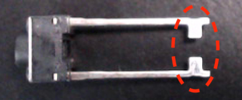
Regardless of whether the leads have metal tabs at the end, you may optionally trim the leads to be about ¼in (6.4mm) long – you can use the exposed lead from a jumper wire as a reference – so that the pushbuttons sit flush on the breadboard. It is not necessary that they sit flush; this is simply to keep the buttons from wiggling under your fingers. Do not cut the leads shorter than ⅛in (3.2mm)!
Caution
Be sure to use eye protection in case the leads’ ends fly off when you snip them.
Install the Buttons
These are “normally open” momentary “switches” that close when pressed and re-open when released. We will wire the pushbuttons such that they normally produce a 1, and when pressed will produce a 0. Fig. 32 shows a diagram of the wiring for the pushbuttons.

Fig. 32 Diagram of wiring associated with momentary pushbutton input.
a |
2-lead pushbuttons |
b |
4-prong pushbuttons |
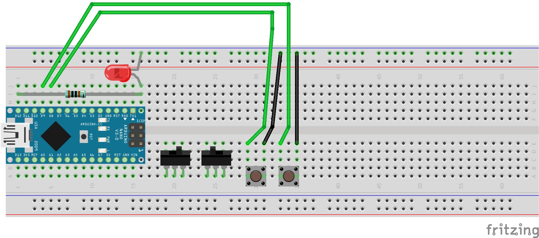
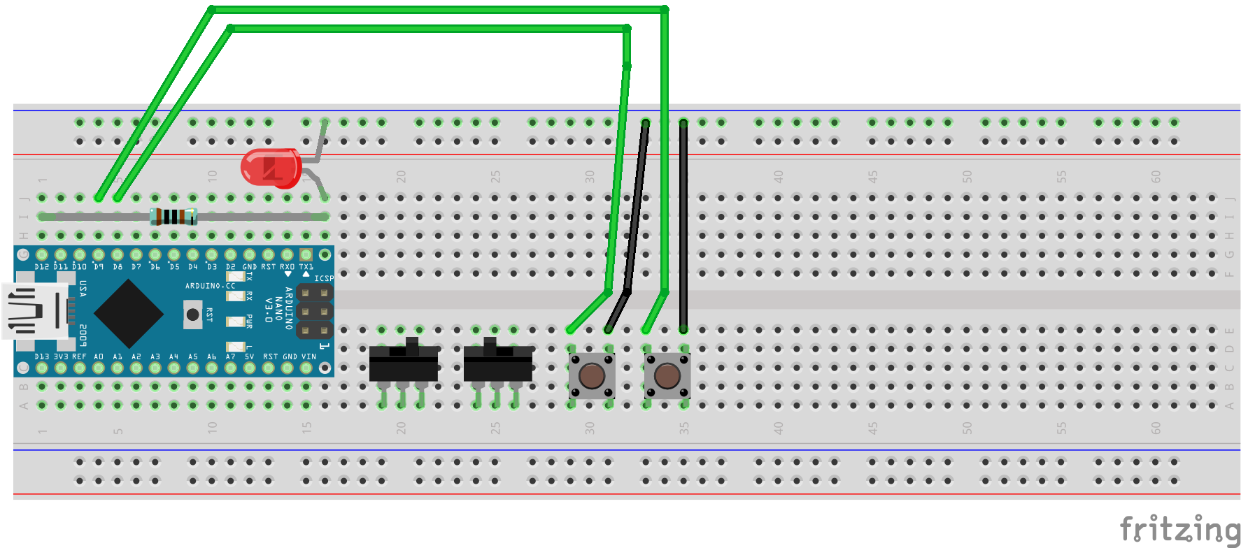
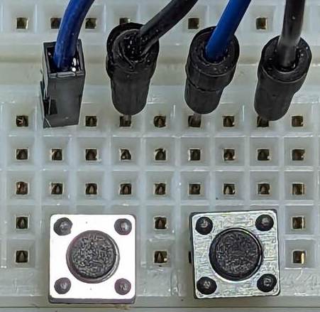
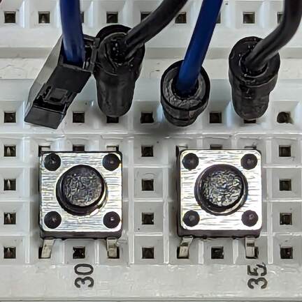
Fig. 33 Wiring the momentary pushbuttons
a |
Pushbuttons with two leads. |
b |
Pushbuttons with four prongs. |
c |
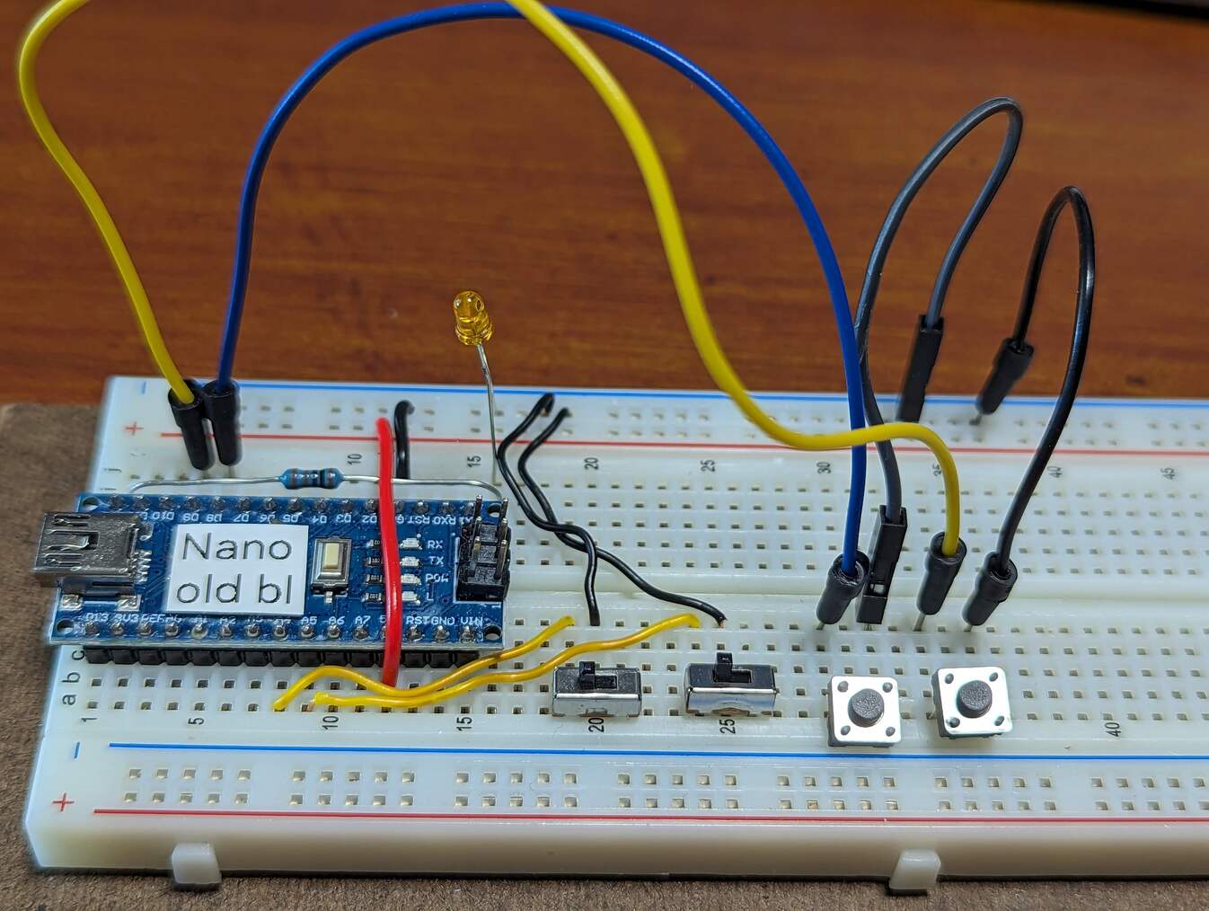
The momentary pushbuttons, wired to the Arduino Nano. |
||
Important
Before proceeding further, disconnect the USB cable from the Arduino Nano.
- :[ ]:
If you have 2-lead pushbuttons:
Insert the leads of one pushbutton into contact points a29 and a31.
Insert the leads of the other pushbutton into contact points a33 and a35.
- :[ ]:
If you have 4-prong pushbuttons:
Insert the prongs of one pushbutton into contact points a29, d29, a31, and d31.
Insert the prongs of the other pushbutton into contact points a33, d33, a35, and d35.
- :[ ]:
Peel off one wire from the male-to-male rainbow cable, and use it to connect contact point e31 to the upper ground (–) rail.
- :[ ]:
Peel off one wire from the male-to-male rainbow cable, and use it to connect contact point e35 to the upper ground (–) rail.
- :[ ]:
Use a wire from the male-to-male rainbow cable to connect the ungrounded side of the left pushbutton to the Arduino Nano: connect e29 to j5.
- :[ ]:
Now use another two wire from the male-to-male rainbow cable to connect the ungrounded side of the right pushbutton to the Arduino Nano: connect e33 to j4
When you have finished setting up the pushbuttons’ wiring, there should be the electrical paths described in Table 23.
Pushbutton |
Arduino Nano pin |
Power/Ground Rail |
|---|---|---|
Left button’s grounded lead |
ground (–) rail |
|
Left button’s ungrounded lead |
|
|
Right button’s grounded lead |
ground (–) rail |
|
Right button’s ungrounded lead |
|
Attention
CHECKPOINT 6 | Before proceeding further, have a TA, a classmate, or a friend verify that you have correctly inserted and wired the momentary pushbuttons. Update your checkpoints.txt file to indicate who checked your work and when they did so.
Connect your Arduino Nano to the computer. In the IDE’s Serial Monitor, notice that Left button is normally UP, but it becomes DOWN when you press the left button. Similarly, Right button is normally UP, but it becomes DOWN when you press the right button.
Notice that both Left LED and Right LED are normally OFF. Position both switches to the right. Notice than when (and only when) the left button is to the right and you’re also pressing the left button, Left LED becomes ON, and the LED labelled “L” on the Arduino Nano illuminates. Similarly, when (and only when) the right button is to the right and you’re also pressing the right button, Right LED becomes ON, and the LED that you installed illuminates.