Insert the Microcontroller into the Breadboard
Cow Pi mk1f: Arduino Nano form factor
A microcontroller, such as the Atmel ATmega328P on the Arduino Nano, is a very simple processor when compared to a microprocessor designed for general-purpose computing. At the same time, a microcontroller has some features not present on a microprocessor, such as built-in analog-to-digital converters (ADCs). [1] A microcontroller board, such as the Arduino Nano, combines the microcontroller with other components [2] in a form factor convenient for experimentation.
The Arduino Nano has a USB port to connect to a computer and/or to provide power to the Arduino Nano. The six upward-pointing pins are used to program the Arduino Nano without using a host computer; we will not use these.
It has thirty downward-pointing pins.
RX0andTX1are used for asynchronous serial communication; as the USB interface also uses the same corresponding pins on the ATmega328P, we will not use these two pins (you will notice that when the Arduino Nano communicates with the host computer, theRXandTXLEDs will illuminate).Pins
D2-D13are digital input/output pins.Pins
A0-A7are analog input pins; however,A0-A5can also be used as digital input/output pinsD14-D19.AREF(analog reference) is used to provide a reference voltage for the ADC (we will not use this pin).Pins
3V3and5Vprovide regulated 3.3 volts and 5 volts for external circuitry;5Vcan also be used to power the Arduino Nano if connected to a regulated 5V power supply.VINcan be used to power the Arduino Nano if connected to an unregulated power supply, such as a 9V battery; the Arduino Nano’s onboard voltage regulator will then provide regulated voltages needed.The
GNDpins are for the common ground; the ground portions of external circuitry and of external power supplies must be electrically connected to the Arduino Nano’s ground.Finally, the
RESETpins will reset the Arduino Nano if grounded (pressing the button in the middle of the Arduino Nano will also reset it). Note that, unlike a general-purpose computer, when a microcontroller is reset it will restart its program when the reset is released.
The ATmega328P microcontroller on the Arduino Nano is an 8-bit processor with 32KB of flash memory for the program and 2KB of RAM for data. While 8-bit logical operations, as well as 8-bit addition and subtraction, can be completed in one clock cycle, multiplication requires two clock cycles (16-bit operations require additional clock cycles). There is no hardware divider, and there is no floating point hardware, so integer division (to include the modulo operation) and all floating point operations are performed in software, requiring hundreds of clock cycles.
If you have already read the first half of Chapter 8, the ATmega328P has separate instruction and data memory, similar to the simple processor design described in the first half of Chapter 8. If you have already read the second half of Chapter 8, the ATmega328P has a 2-stage pipeline (with Fetch and Execute stages). If you have already read Chapter 10, the ATmega328P does not have cache memory; however, the data memory is SRAM, the same memory technology used in microprocessors’ memory caches. If you have already read Chapter 10, the ATmega328P does not have a memory management unit for virtual memory; instead, the ATmega328P uses only physical addressing.
Breadboard Terminology
Tip
If you are not familiar with solderless breadboards, read the Breadboards for Beginners Guide at adafruit.com.
The How to Use a Breadboard Tutorial at sparkfun.com is also informative.
Even though breadboards are often viewed in “landscape” orientation (such as in the photo in the inventory and as seen in the diagram figures) instead of “portrait” orientation, the numbered sections are called rows and the lettered sections are called columns. In the interest of preserving common usage, we will use this terminology. We will refer to specific contact points using the letter-number combination.
Install the Arduino Nano onto the Breadboard
- :[ ]:
Orient the breadboard in front of you so that row 1 is on your left and row 63 is on your right; column a should be at the bottom, and column j should be at the top.
- :[ ]:
Remove the anti-static foam from the Arduino Nano’s pins.
You will place the Arduino Nano on the left side of the breadboard with the USB connector on the left (that is, facing away from the breadboard).
- :[ ]:
Position the upper row of pins on contact points g1-g15 and the lower row of pins on contact points c1-c15.
- :[ ]:
Double-check that:
the pin labeled
D12is in the upper-left, on contact point g1the pin labeled
D13is in the lower-left, on contact point c1the pin labeled
VINis in the lower-right, on contact point c15the pin labeled
TX1is in the upper-right, on contact point g15
- :[ ]:
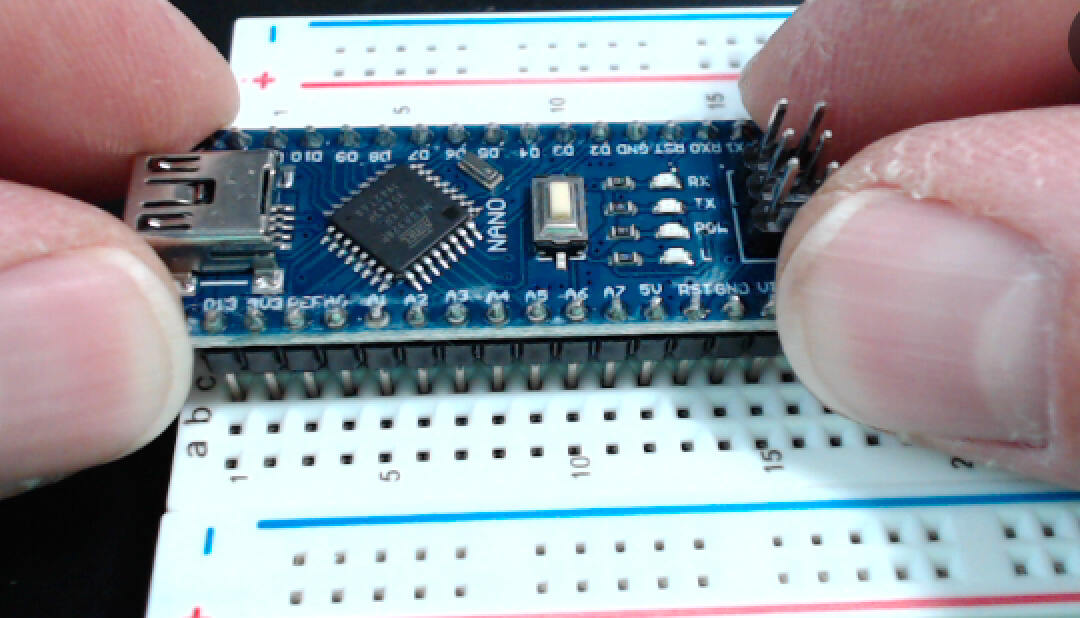
Gently press on both ends of the Arduino Nano to insert the pins into the contact points, using a slight rocking motion if necessary (Fig. 41(a)).
- :[ ]:
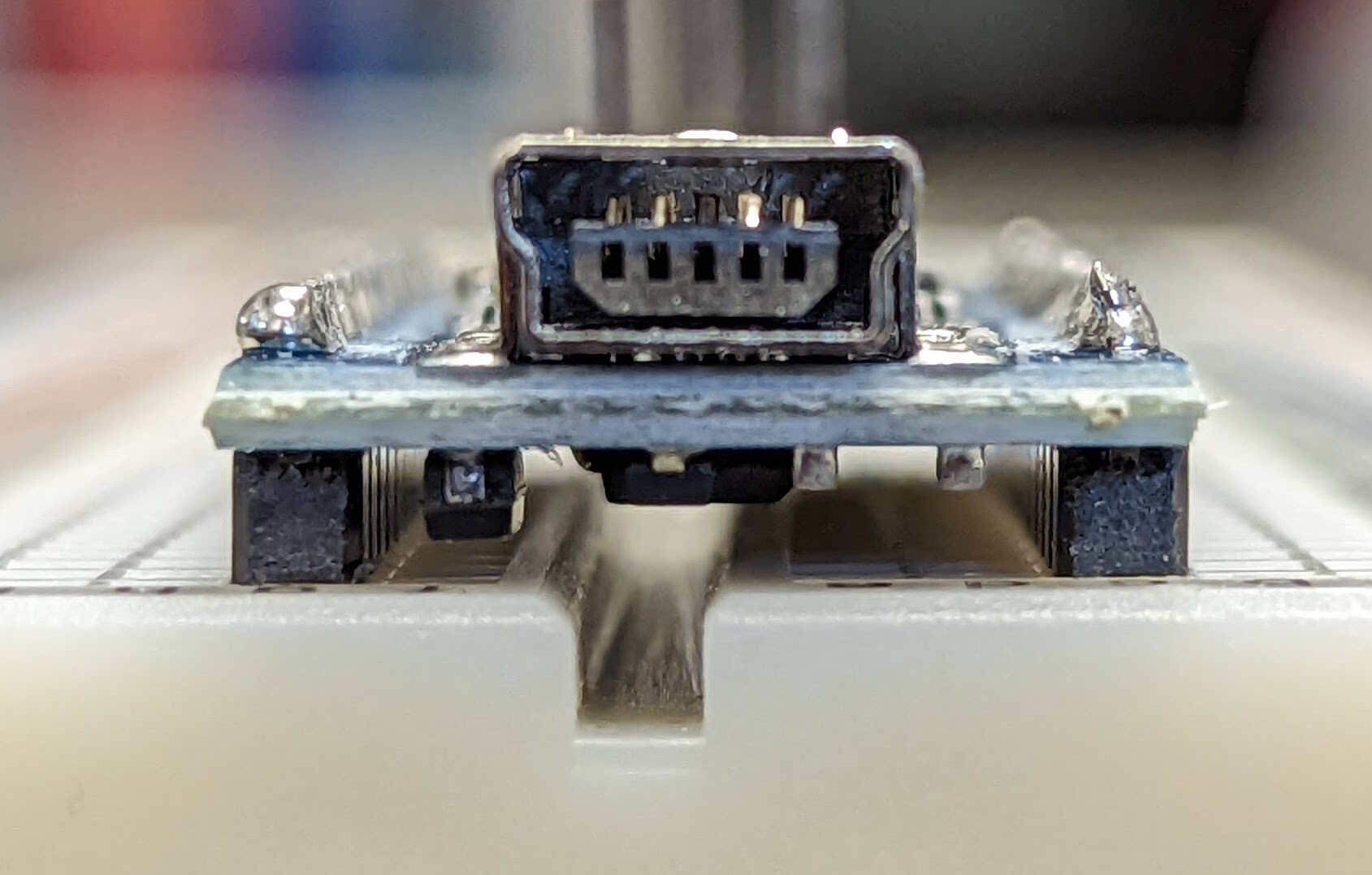
Press the Arduino Nano into the breadboard until it physically cannot be inserted any deeper (Fig. 41(b)).

Fig. 41 Inserting the microcontroller board into the breadboard.
a |
b |
|---|---|
|
|
Press gently on both ends of the microcontroller board. |
A microcontroller board fully inserted. |
Attention
CHECKPOINT 1 | Before proceeding further, have a TA, a classmate, or a friend verify that you have correctly inserted the Arduino Nano into the breadboard. Update your checkpoints.txt file to indicate who checked your work and when they did so.