Install the Display Module
Cow Pi mk1e: Arduino Nano form factor, SPI communication
Examine the 7-segment display module.
Notice that the header has 5 pins (Fig. 37): VCC (common collector voltage), GND (ground), DIN (data in), CS (chip select), and CLK (clock).
When the display module is oriented for viewing, these header pins will be on the left.
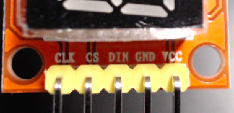
Fig. 37 The display module’s header has 5 pins.
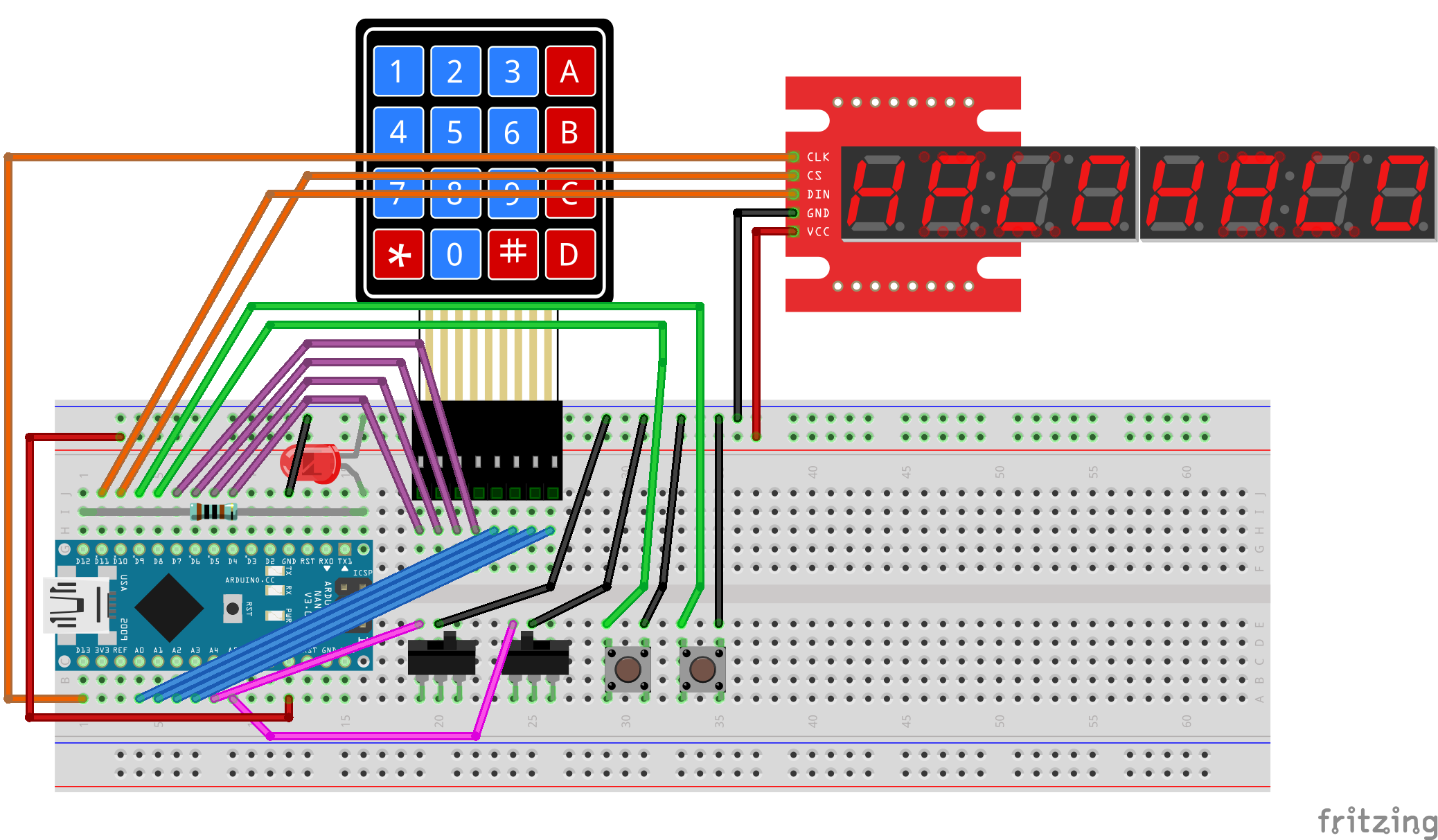
Fig. 38 shows a diagram of the wiring to connect the display module to the breadboard.
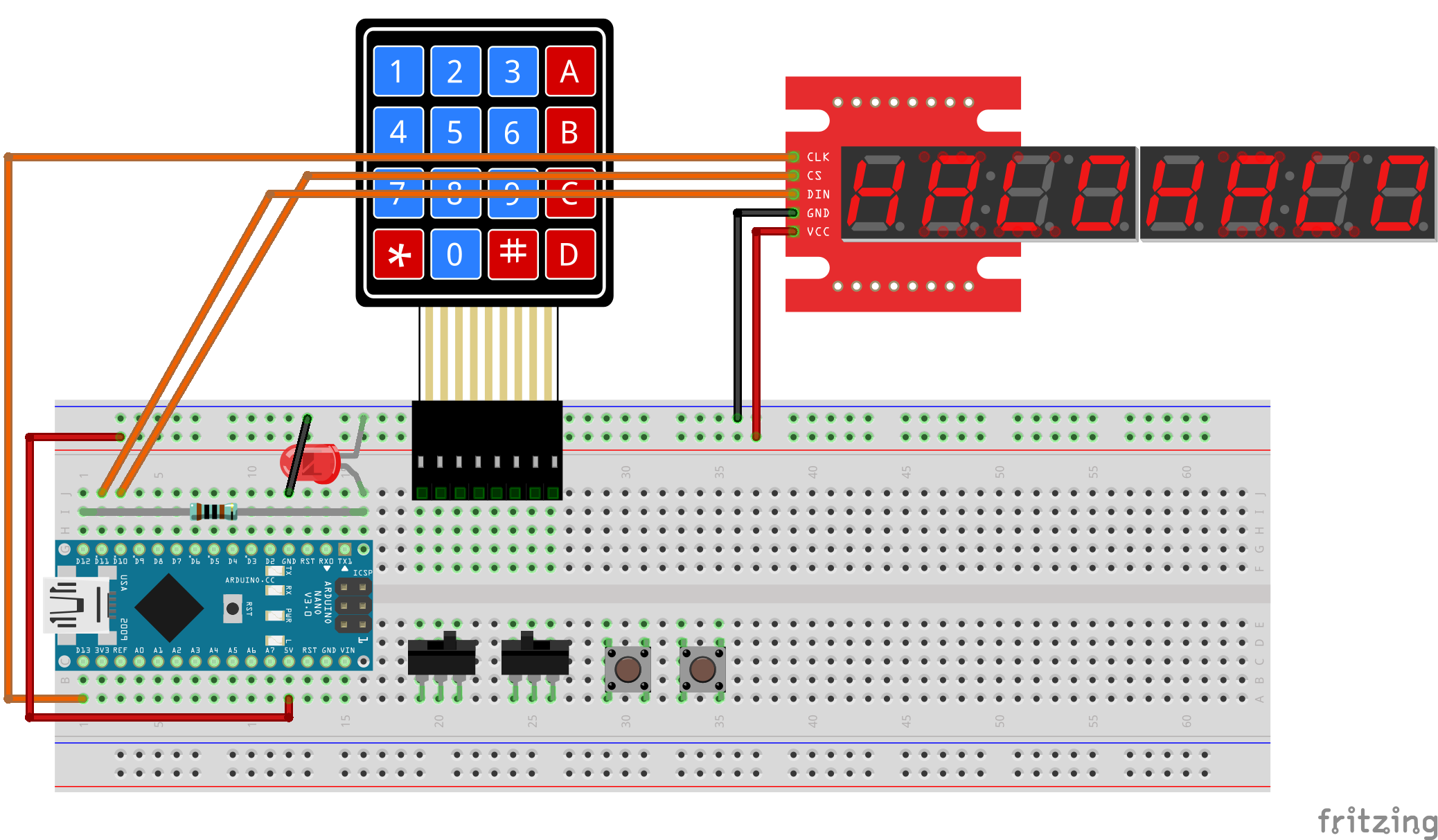
Fig. 38 Diagram of display module’s connections to the breadboard.
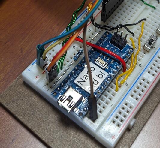
Fig. 39 SPI connections on at the microcontroller.
Important
Before proceeding further, disconnect the USB cable from the Arduino Nano.
- :[ ]:
Look at Fig. 40 to determine which display module you have:

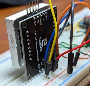
Fig. 40 Display modules that use the Serial-Parallel Interface protocol
a |
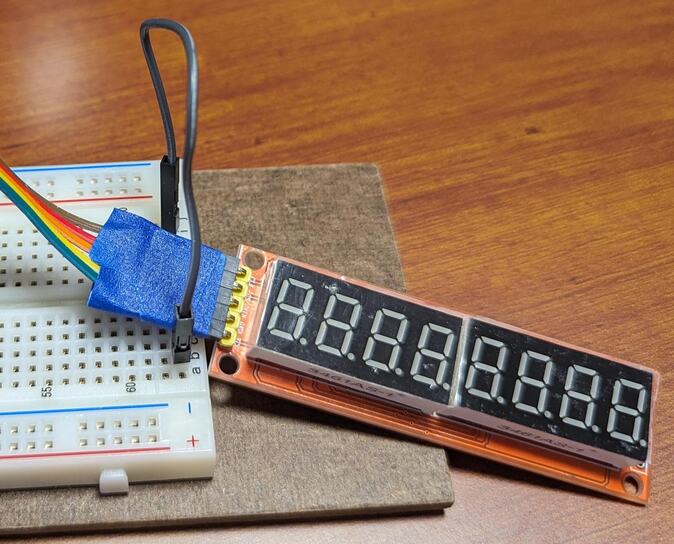
MAX7219-driven 8-digit/7-segment display. |
||
b |
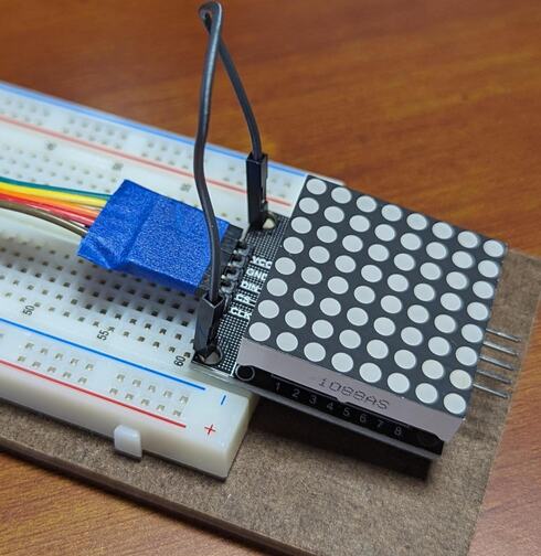
MAX7219-driven LED matrix display. |
c |
|
If you have an 8-digit/7-segment display (Fig. 40(a)):
- :[ ]:
Take the 5-conductor female-to-male rainbow cable and attach the 5 female connectors to the display module’s 5 header pins.
- :[ ]:
Optionally loop a wire from breadboard row 63(a-e) to row 63(f-j) as shown in Fig. 40(a) to keep the display module from sliding around.
If you have an LED matrix display, you can either let it float free (Fig. 40(b)) or pin it to the breadboard (Fig. 40(c))
If you let it float free:
- :[ ]:
Take the 5-conductor female-to-male rainbow cable and attach the 5 female connectors to the display module’s 5 header pins. Be sure that you attach the cable to the side of the display module that has a
DINpin.- :[ ]:
Optionally loop a wire from breadboard row 63(a-e) to row 63(f-j) as shown in Fig. 40(a) to keep the display module from sliding around.
If you pin it to the breadboard:
- :[ ]:
Determine which side of the display module has a
DINpin. Insert the pins on that side into 5 adjacent breadboard rows.- :[ ]:
Take a 5-conductor male-to-male rainbow cable and insert one end into the same rows as the display module’s 5 header pins.
- :[ ]:
Identify the wire that is connected to the display module’s
CLKpin; insert the male end of this wire in contact point a1 (electrically connected to the Arduino Nano’sD13pin).- :[ ]:
Insert the male end of the
DINwire into contact point j2 (electrically connected to the Arduino Nano’sD11pin).- :[ ]:
Insert the male end of the
CSwire into contact point j3 (electrically connected to the Arduino Nano’sD10pin).- :[ ]:
Insert the
GNDwire into the upper ground (–) rail, and theVCCwire into the upper power (+) rail.
When you have finished connecting the display module, there should be the electrical connections described in Table 25.
Display Module pin |
Arduino Nano pin |
Power/Ground Rail |
|---|---|---|
|
|
|
|
|
|
|
|
|
|
ground (–) rail |
|
|
power (+) rail |
Attention
CHECKPOINT 8 | Before proceeding further, have a TA, a classmate, or a friend verify that you have correctly connected the display module to the breadboard. Update your checkpoints.txt file to indicate who checked your work and when they did so.
If you have an 8-digit/7-segment display:
If you are using the Arduino IDE:
- :[ ]:
Open the File ⟶ Examples ⟶ CowPi_stdio ⟶ max7219_seven_segment example.
If you are using PlatformIO:
- :[ ]:
Create a new project named DisplayTest with the appropriate board selection for your Arduino Nano. Without removing anything from your platformio.ini file, add the following to your platformio.ini file, replacing
▶environment_name◀with the environment name that PlatformIO created automatically for you:[platformio] src_dir = .pio/libdeps/▶environment_name◀/CowPi_stdio/examples/max7219_seven_segment [env] lib_deps = docbohn/CowPi @ ^0.6.0 docbohn/CowPi_stdio @ ^0.6.0 monitor_echo = yes
- :[ ]:
Compile the program and upload it to your Arduino Nano.
You should see a “Hello, world!” message. If so, then you have correctly connected the display module.
If you have an LED matrix display:
If you are using the Arduino IDE:
- :[ ]:
Open the File ⟶ Examples ⟶ CowPi_stdio ⟶ max7219_dotmatrix example.
If you are using PlatformIO:
- :[ ]:
Create a new project named DisplayTest with the appropriate board selection for your Arduino Nano. Without removing anything from your platformio.ini file, add the following to your platformio.ini file, replacing
▶environment_name◀with the environment name that PlatformIO created automatically for you:[platformio] src_dir = .pio/libdeps/▶environment_name◀/CowPi_stdio/examples/max7219_dotmatrix [env] lib_deps = docbohn/CowPi @ ^0.6.0 docbohn/CowPi_stdio @ ^0.6.0 monitor_echo = yes
- :[ ]:
Compile the program and upload it to your Arduino Nano.
You should see a “Hello, world!” message. If so, then you have correctly connected the display module.
Kit Assembly is Complete
You have now finished assembling the class kit. In the upcoming I/O labs, you will use the kit to learn about memory-mapped I/O and about handling low-level interrupts.