Input Devices
Unless implementing Expansion Options, all inputs in the Cow Pi circuit are either simple passive input devices, described here, or timers that are part of the microcontroller, described in the Microcontroller-Specific Details Section.
Switches and Buttons
There are two pushbuttons and two slide-switches in the Cow Pi circuit.
Theory of Operation
The pushbuttons, or tactile switches,[1] are normally-open, momentary switches. When a button is in the “up” position, that is, it is not being pressed, there is an open circuit between the contacts. When the button is pressed and is in the “down” position, it closes the circuit between the contacts.

Fig. 6 The pushbuttons used in the Cow Pi are normally-open, momentary switches.
The slide-switches are technically single-pole, double-throw switches, but we treat them as single-pole, single-throw switches. In the Cow Pi circuit, when a switch is in the “right” position, there is an open circuit between the contacts. When the switch is in the “left” position, it closes the circuit between the contacts.

Fig. 7 We treat the slide-switches used in the Cow Pi as single-pole, single-throw switches.
As shown in Fig. 8, the devices are placed in the circuit with one pole grounded and the other attached to a microcontroller input pin. The microcontroller is configured to place its operating voltage on the pin with a “pull-up resistor.” This pull-up resistor has a very high resistance, typically 10kΩ-20kΩ, so that when the switch is closed, only a very small amount of current flows.

Fig. 8 Tactile switches and slide switches have one pole grounded and the other connected to a pin with a pull-up resistor.
When the circuit is open (button in the “up” position or slide-switch in the “right” position), no current flows through the resistor. Because no current flows through the resistor, there is no voltage drop across the resistor, and so the voltage measured at the pin is the microcontroller’s operating voltage. As shown in Fig. 9, This is interpreted as logic high (boolean 1).
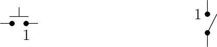
Fig. 9 When a switch is open, the pin reads high.
On the other hand, when the circuit is closed (button in the “down” position or slide-switch in the “left” position), current flows through the resistor. Because there is no other appreciable resistance in the circuit, all of the voltage drop is across the resistor, and so 0V is measured at the pin. As shown in Fig. 10, This is interpreted as logic low (boolean 0).

Fig. 10 When a switch is closed, the pin reads low.
Reading the Devices’ Positions
To read these input devices, the pins must be configured as input pins with the microcontroller’s internal pullup resistors enabled.
(Alternatively, external pullup resistors could be used – but won’t be in the Cow Pi for passive input devices.)
The CowPi library’s cowpi_setup() function takes care of this along with other configuration settings.
That done, reading a devices’ position is as simple as reading the pin’s logic value.
If you are not writing code using memory-mapped I/O, then you would do this with Arduino’s digitalRead() function or the Raspberry Pi SDK’s gpio_get() function.
If you are writing code using memory-mapped I/O, then you would examine the pin’s bit in the I/O bank’s input register, as described in the Microcontroller-Specific Details Section.
If the bit’s value is 0, then the button is pressed, or the switch is in the left position.
If the bit’s value is 1, then the button is not pressed, or the switch is in the right position.
To Learn More
SparkFun has a webpage that discusses Button and Switch Basics.
Matrix Keypad
The numeric keypad consists of sixteen keys, labeled 0-9, A-D, #, and *.
Rather than requiring sixteen distinct pins on the microcontroller (one for each key), it is wired so that it only requires eight pins: one for each column and one for each row.
Theory of Operation
Each key on a matrix keypad is a normally-open, momentary button that resides at the intersection of a row and a column; see Fig. 11. When pressed, the key closes an electrical connection between that row and column. On the Cow Pi, each row is connected to an output pin on the microcontroller, and each column is connected to an input pin with a pull-up resistor.

Fig. 11 Each key on the keypad is at the intersection of a row and a column.
Because the input pins that the columns are connected to use pull-up resistors, the logic value on these pins will normally read high (boolean 1). A column will read as logic low (boolean 0) only when it is electrically connected to a row that is set low. An application developer can take advantage of this by setting all of the rows’ pins to logic low (boolean 0); see Fig. 12. When a key is pressed, its column will then become low.
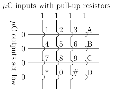
Fig. 12 Detecting a keypress is possible by setting each row low and monitoring whether any column becomes low.
A keypress, thus, can be detected based on the values read from the columns’ pins. An application programmer can poll the four columns’ pins. If, collectively, they produce the bit vector 0xF, then no key is being pressed; however, if the bit vector is anything other than 0xF (such as in Fig. 13, then at least one key is being pressed. As an alternative to polling, an interrupt that is triggered by a change on the columns’ pins can be used to indicate that a key has been pressed (see the Section discussing Interrupts).
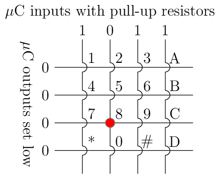
Fig. 13 Pressing a key, such as “8”, causes the column bit vector to be something other than 0xF.
Once it has been determined that a key is pressed, code that scans the keypad should execute. If every row is made logic-high except for one row, then the code can determine whether the key that was pressed is in that row. For example, as shown in Fig. 14, if the “8” key is pressed and “row4” is the only logic-low row, then the column bit vector is 0xF, and so the pressed key is not in that row.
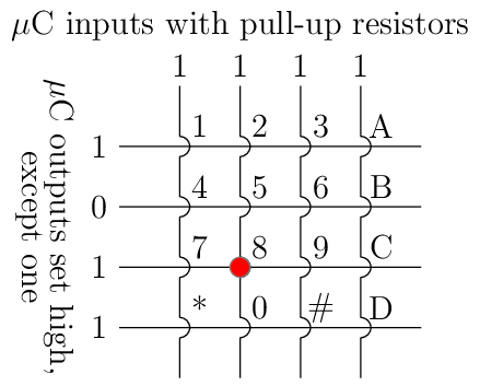
Fig. 14 Examining a row that does not have a pressed key.
But, as shown in Fig. 15, if “row7” is the only logic-low row, then the column bit vector is not 0xF, and so the pressed key is in that row; moreover, because “col2” is now logic-low, the code can establish that the pressed key is at the intersection of “row7” and “col2,” i.e., the “8” key.
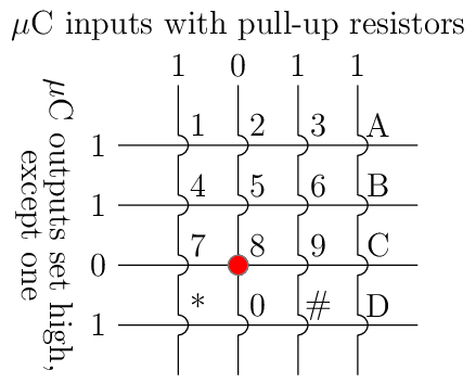
Fig. 15 Examining a row that does have a pressed key.
After the code has determined which row and column the pressed key is on, it can return a value or assign a value to a variable accordingly.
This might be a char corresponding to the character on the key’s face, as is the case for cowpi_get_keypress().
Or this might be an int corresponding to the value of the numeral on the key’s face.
Or this might even be some value unrelated to whatever is printed on the key’s face.
Scanning the Keypad
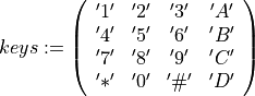
There are a few options for obtaining the value corresponding to a key that is pressed on the keypad. The most efficient for a simple application is to use a lookup table. For example, if you need to return a character that corresponds to the face value of the key that was pressed, then the lookup table would be:
If the keypad is wired to the microcontroller such that four output pins are connected to the rows and four input pins are connected to the columns (as is the case for the Cow Pi), then this pseudocode will scan the keypad and determine which key, if any, is pressed.
1for each ROW do
2    set output pin for each row to 1
3    set output pin for ROW to 0
4    wait at least one microsecond
5    for each COLUMN do
6        column_bit := the value on input pin for COLUMN
7        if (column_bit = 0) then
8            key_pressed := keys(ROW,COLUMN)
9set output pins for each row to 0       (* to detect the next keypress *)
Note
This pseudocode will report at most one key pressed; it would have to be modified to report multiple keys pressed. (Mark 1 Cow Pis’ hardware does not support multiple key presses, though mark 3 & 4 Cow Pis do.)
Tip
The for each expressions in the pseudocode should be understood to be the mathematical  operator.
Write a loop, or don’t, based on what makes sense to you in terms of readability and ease of modification.
We have seen successful implementations that use a loop to iterate over the columns,
and we have seen successful implementations that instead have a
operator.
Write a loop, or don’t, based on what makes sense to you in terms of readability and ease of modification.
We have seen successful implementations that use a loop to iterate over the columns,
and we have seen successful implementations that instead have a switch statement or four if statements.
The delay shown in line 4 is sometimes, but not always necessary. The construction of some Cow Pi circuits (particularly mark 1 & 2 models) results in sufficient parasitic reactance that there is a detectable delay between setting a pin’s output value and being able to detect the change when reading a different pin’s input value. Some realizations of the pseudocode attempt to read the change before it can be read reliably; this usually manifests as one of the keypad’s columns not being readable. The fix is to introduce a delay. Often, one microcontroller clock cycle is sufficient; however we have (rarely) seen constructions with sufficient parasitic reactance that a delay of more than one microsecond (but less than two) is necessary.
We recommend a delay of 1µs, which generally should be sufficient regardless of the particular Cow Pi model, microcontroller, and construction quality. If you find that 1µs is insufficient, then introduce a 2µs delay. This delay should be managed with a busy-wait until at least 1µs has elapsed.