Install the Light-Emitting Diode
Cow Pi mk1e: Arduino Nano form factor
You will now connect an external LED. An LED is a light emitting diode, and like all diodes it allows current to flow only in one direction. As shown in Fig. 23, one lead on the LED is longer than the other, and this tells us which direction current will flow. When we insert the LED into the circuit, power will flow from one of the Arduino Nano’s pins through the LED to ground. Most LEDs have so little internal resistance that, unless current is otherwise limited, enough current will flow through the LED to destroy the semiconductor material. The typical solution, which we will use, is to employ a current-limiting resistor. (If you look very closely at your Arduino Nano, you will see a tiny surface-mount resistor next to each built-in LED.)
Fig. 24 shows a diagram of the components you will install for the LED output.
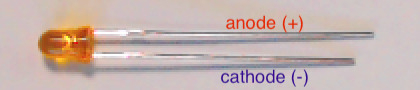
Fig. 23 The LED’s longer lead connects to power; the shorter lead connects to ground.

Fig. 24 Diagram of component assembly for LED output.
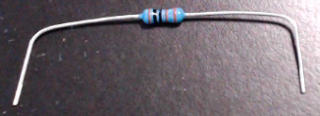
Fig. 25 Bend the resistor’s leads about 1cm from the ends.
Important
Before proceeding further, disconnect the USB cable from the Arduino Nano.
- :[ ]:
Take the 1k
 resistor and place a right-angle bend in each lead about 0.4in (1cm) from the ends
(we want the remaining length to be about 1.5in (3.8cm) – you do not need to be exact; [1]
the leads are flexible enough that you only need to be approximate) – see Fig. 25.
resistor and place a right-angle bend in each lead about 0.4in (1cm) from the ends
(we want the remaining length to be about 1.5in (3.8cm) – you do not need to be exact; [1]
the leads are flexible enough that you only need to be approximate) – see Fig. 25.- :[ ]:
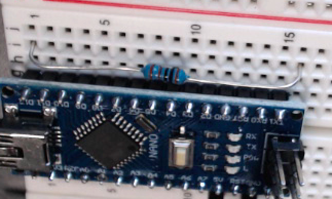
Insert one of the resistor’s leads into contact point i1 (electrically connected to the Arduino Nano’s
D12pin in g12) and the other into contact point i16.- :[ ]:
Gently press along the length of the resistor, causing the leads to deform slightly, until the resistor’s height above the breadboard is about the same as the Arduino Nano’s printed circuit board. See Fig. 26(a).
- :[ ]:
Take the LED and spread the leads apart slightly.
- :[ ]:
Insert the longer lead (the anode) in contact point j16, and the shorter lead (the cathode) in the upper ground (–) rail. See Fig. 26(b).

Fig. 26 Constructing the LED assembly.
a |
b |
|---|---|
|

|
The resistor run between contact points i1 and i16. |
The LED’s longer lead in in contact point j16,
and the shorter lead is in the upper ground (–) rail.
|
When you have finished installing the external LED, there should be the electrical connections described in Table 25.
Read each of this and subsequent tables’ rows as describing which electrical components are connected to which other components.
For example, the LED’s anode is connected to the resistor’s right lead;
the LED’s cathode is connected to ground;
and the resistor’s left lead is connected to the Arduino Nano’s D12 pin.
LED lead |
Resistor lead |
Arduino Nano pin |
Power/Ground Rail |
|---|---|---|---|
Anode |
Right |
||
Cathode |
ground (–) rail |
||
Left |
|
Attention
CHECKPOINT 4 | Before proceeding further, have a TA, a classmate, or a friend verify that you have correctly installed the LED and its current-limiting resistor. Update your checkpoints.txt file to indicate who checked your work and when they did so.
- :[ ]:
In your IDE, load your MyBlink project.
- :[ ]:
In the
pinMode()and the twodigitalWrite()calls, replace theLED_BUILTINargument with12:void setup(void) { pinMode(12, OUTPUT); } void loop(void) { digitalWrite(12, HIGH); delay(250); // or whatever value you used digitalWrite(12, LOW); delay(1500); // or whatever value you used }
- :[ ]:
Re-connect the USB cable to your Arduino Nano.
- :[ ]:
Compile the program and upload it to your Arduino Nano.
Now, instead of the built-in LED, the external LED that you installed will blink.