Install the Matrix Keypad
Cow Pi mk1e: Arduino Nano form factor, SPI communication
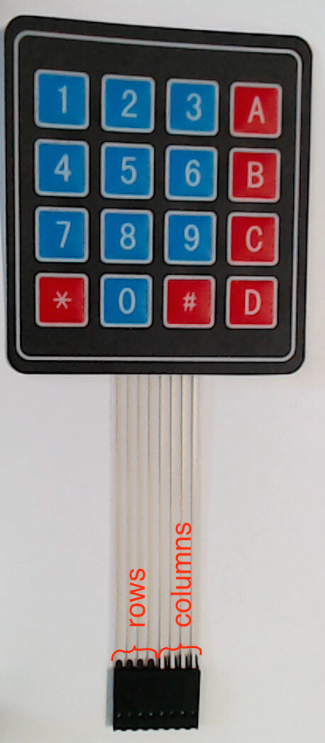
Observe that the matrix keypad has sixteen buttons has eight pins in its female connector.
As shown in Fig. 34(a), when the keypad is face-up and oriented for reading, the four pins on the left are the row pins, and the four pins on the right are the column pins.
From left-to-right, we will name these pins row1, row4, row7, row*, column1, column2, column3, columnA.
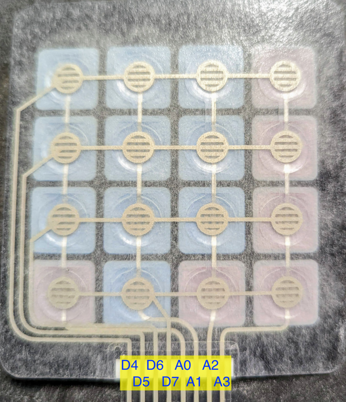
Fig. 34(b) shows the membrane contacts and which Arduino Nano pin will be connected to each keypad pin.

Fig. 34 The numeric keypad’s header has four row pins and four column pins
a |
b |
|---|---|
|
|
Front of matrix keypad. |
Keypad’s underlying contact matrix. |
Fig. 35 shows a diagram of the wiring for the matrix keypad.
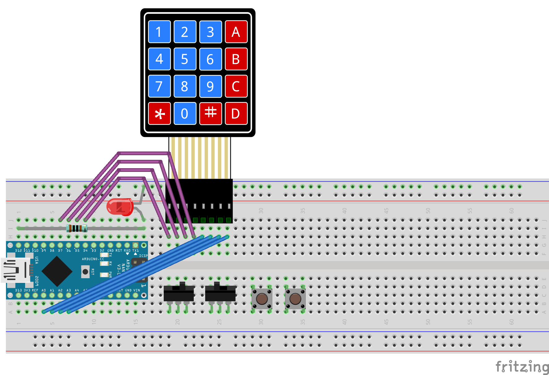
Fig. 35 Diagram of wiring associated with matrix keyboard input.
Important
Before proceeding further, disconnect the USB cable from the Arduino Nano.
- :[ ]:
If your 8-pin male-male header strip is not already inserted into the keypad’s female connectors, insert it into the female connectors now. If your male-male header strip has more than eight pins, position the excess pins to the right of the column pins.
- :[ ]:
Connect your keypad to your breadboard such that
row1is in contact point j19, andcolumnAis in contact point j26 (and any unused pins on the male-male header are in contact points j27, j28, etc.).Tip
If you used 20cm wires to connect your slide-switches and/or pushbuttons to the Arduino Nano, then you can use the matrix keypad’s ribbon cable to pull these wires away from the circuit, reducing clutter near the controls.
- :[ ]:
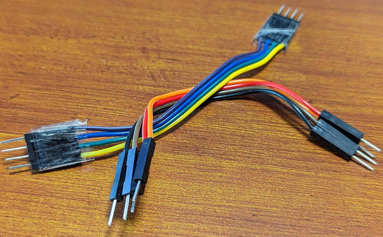
Peel off two 4-conductor cables from the male-to-male rainbow cable. While you can use individual wires, having these 4-conductor cables will simplify keeping track of the wires.
Tip
Taping the each ends’ four leads together may make it easier to manage the 4-conductor cables. (It is not necessary that you do so.) Ordinary household adhesive tape will suffice.
- :[ ]:
Insert one end of one of the 4-conductor cables in contact points h19-h22, in the same breadboard rows as the keypad’s row pins.
- :[ ]:
Insert the other end of the cable in contact points j9-j6.
You want the Arduino Nano’s
D4pin to connect to the keypad’srow1pin,D5torow4,D6torow7, andD7torow*; you can use the wires’ colors to make sure that you do so.- :[ ]:
Insert one end of another 4-conductor cable in contact points h23-h26, in the same breadboard rows as the keypad’s column pins.
- :[ ]:
Insert the other end in contact points a4-a7 (electrically connected to the Arduino Nano’s
D14/A0-D17/A3pins).You want the Arduino Nano’s
D14/A0to connect to the keypad’scolumn1pin,D15/A1tocolumn2,D16/A2tocolumn3, andD17/A3tocolumnA; you can use the wires’ colors to make sure that you do so.
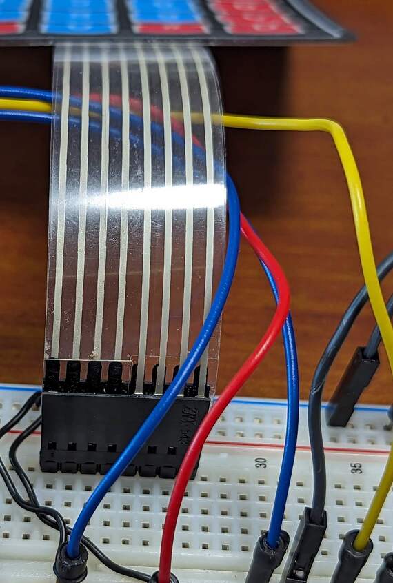
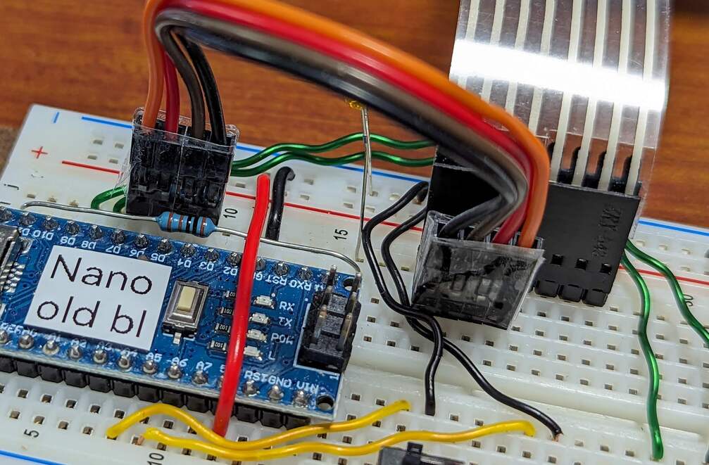
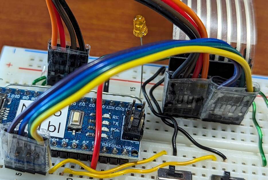
Fig. 36 The matrix keypad, wired to the Arduino Nano
a |
b |
|---|---|
|
|
Wiring the rows. |
Wiring the columns. |
When you have finished setting up the keypad wiring, there should be the electrical paths described in Table 28.
Keypad pin |
Arduino Nano pin |
|---|---|
|
|
|
|
|
|
|
|
|
|
|
|
|
|
|
|
Attention
CHECKPOINT 7 | Before proceeding further, have a TA, a classmate, or a friend verify that you have correctly inserted and wired the matrix keypad. Update your checkpoints.txt file to indicate who checked your work and when they did so.
Warning
Do not press more than one key on the matrix keypad at a time. There are certain combinations of keys that could result in a short-circuit from power to ground, possibly damaging your Arduino Nano. Your Arduino Nano has some safety measures to prevent damage in that situation, but it would be better for you not to test those safety measures.
Connect your Arduino Nano to the computer.
In the IDE’s Serial Monitor,
notice that there is normally no character after Keypad:, and that
Column pins is normally 1111.
Press the 5 key on the matrix keypad.
Notice that the first line of the message from the Arduino Nano is now
Keypad: 5 Column pins: 1011
In general, when you press a key on the keypad, the corresponding character will be displayed after Keypad:.
When you press 1, 4, 7, or *, Column pins becomes 0111;
similarly, pressing a key in the  column causes Column pins to become 1011;
in the
column causes Column pins to become 1011;
in the  column, 1101;
and in the
column, 1101;
and in the  column, 1110.
Be sure to test all 16 keys.
column, 1110.
Be sure to test all 16 keys.