Prepare to Assemble the Cow Pi mark 1f
Inventory the Hardware
Examine the contents of your class kit. It contains:
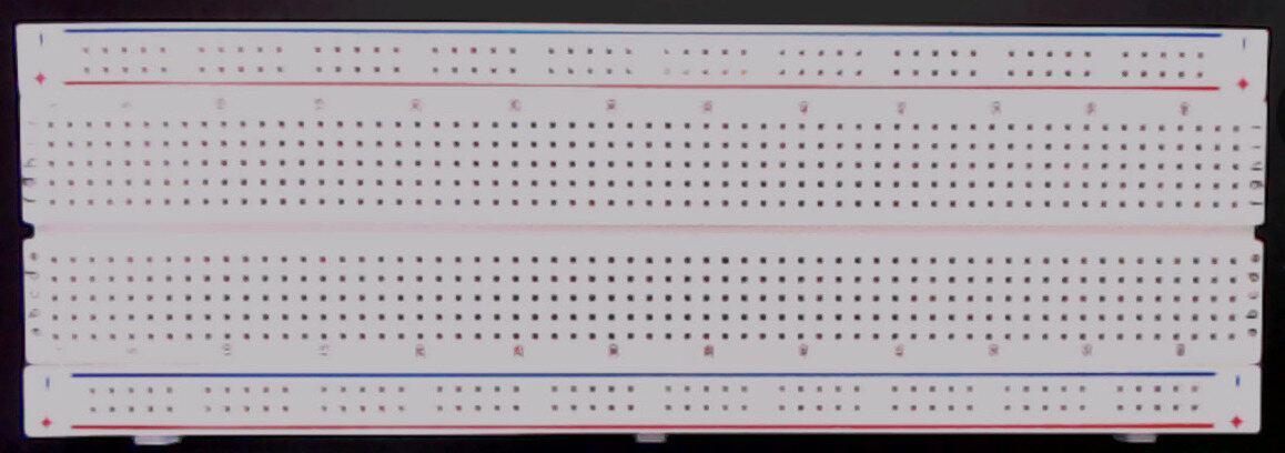
- One (1) full-sized solderless breadboard
- One (1) Arduino Nano (or clone) microcontroller board

- One (1) USB cable (mini-USB shown; yours may be different)

- One (1) 4 × 4 matrix keypad
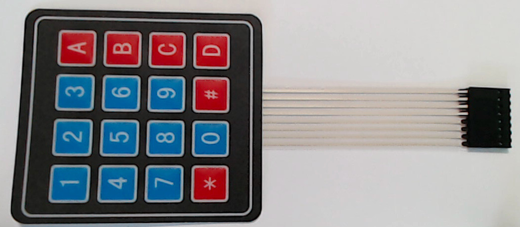
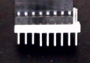
- One (1) 8-pin male-male header strip (might already be inserted into keypad’s female connectors; might have more than 8 pins)
 or
or 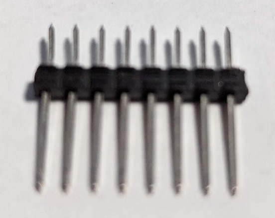
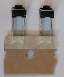
- Two (2) breadboard-mount momentary pushbuttons, aka tactile switches; these might have two leads (which might or might not be attached to cardboard strip), or they might have 4 prongs
 or
or 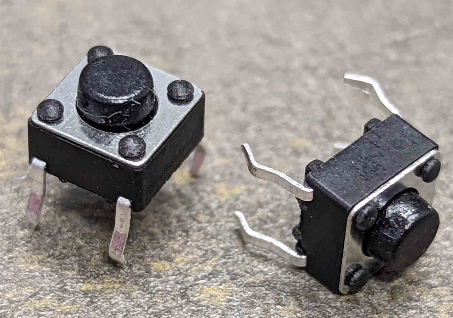
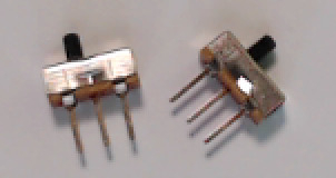
- Two (2) breadboard-mount slide switches
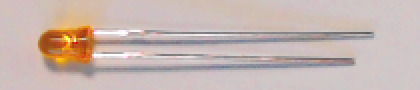
- One (1) Light Emitting Diode (LED) (color may be different than shown)
- One (1) 1k
 resistor
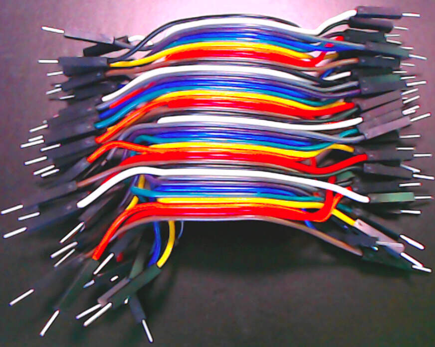
- One (1) 40-conductor 10cm “rainbow” cable (male-to-male),or One (1) 20-conductor 10cm “rainbow” cable (male-to-male) and one (1) 20-conductor 20cm “rainbow” cable (male-to-male)
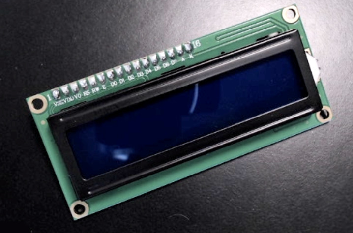
- One (1) 2 × 16 character LCD display module
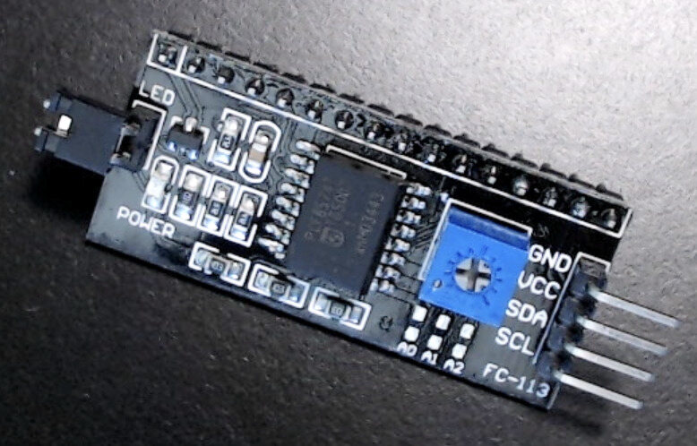
- One (1) I2C Serial Interface (might be attached to display module)
 or
or 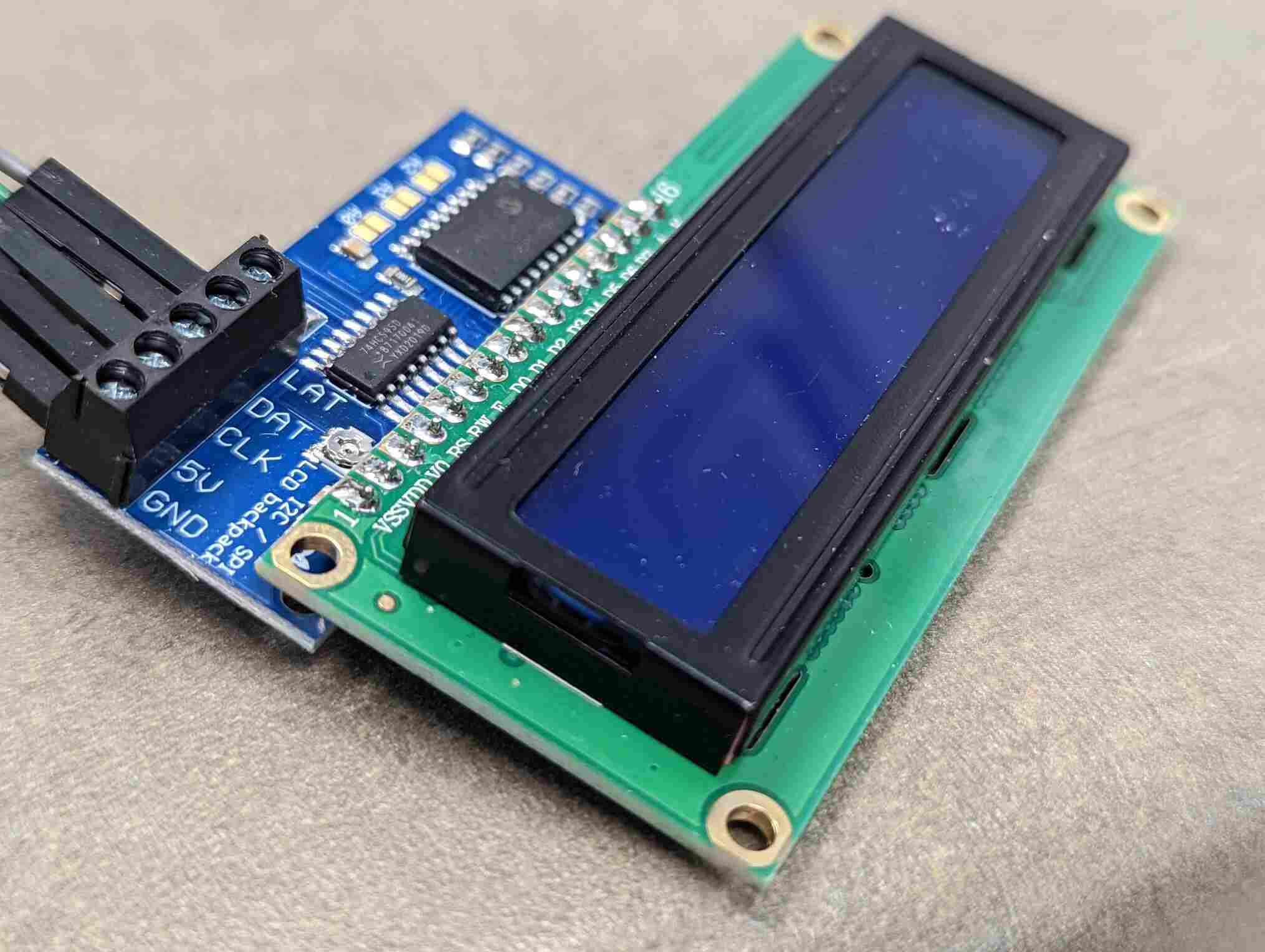 or
or 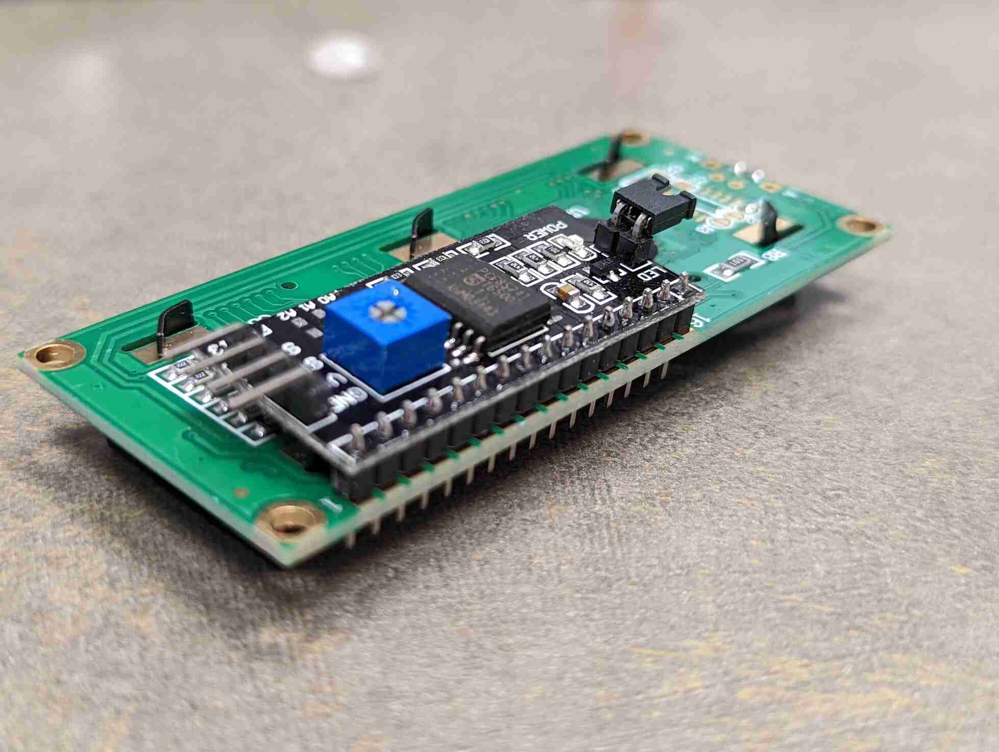
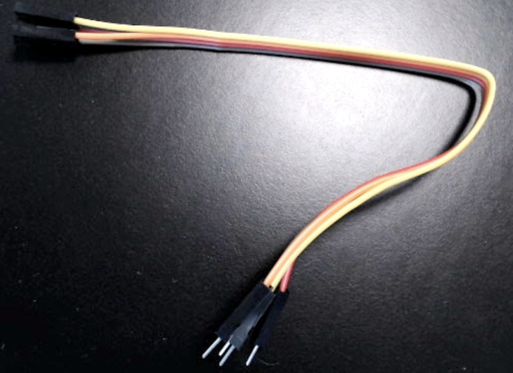
- One (1) 4-conductor 20cm “rainbow” cable (female-to-male)
Not included: when you Install the Display Module, you will briefly need a Phillips-head screwdriver. If you do not have one, I have placed one at the TA desk in the Student Resource Center. [1]
There may be other items in the class kit. Set these aside; you will not need them for this prelab, though they may be used in a specific lab.
Assembling the Class Kit
You will assemble the hardware in the following steps. At various checkpoints, you should pause to have a TA, a classmate, or a friend double-check your work. When you do so, update the checkpoints.txt file to indicate who checked your work and when they did so.
You may want to store your partially- and fully-completed kit in a plastic food container or some other container to prevent jumper wires from being pulled out while in your backpack.
Note
The following pages include diagrams and some photographs of the assembly. The wire colors in the diagrams do not match the wire colors in the assembly. The wire colors in the diagrams are coded by the purpose they serve, whereas the wire colors in the photographs are the colors of wires removed from the male-to-male rainbow cable.
Note
The circuit you build by following these instructions will look a bit like a rat’s nest by the time that you are finished. This is because the jumper wires you remove from the male-to-male rainbow cable are not cut to length and generally will be longer than they need to be (which is much better than being shorter than they need to be). If you have prior experience with building circuits on a solderless breadboard, and if you have solid-core wires and wire cutters, then optionally you may build the circuit with cut-to-length solid core wires.
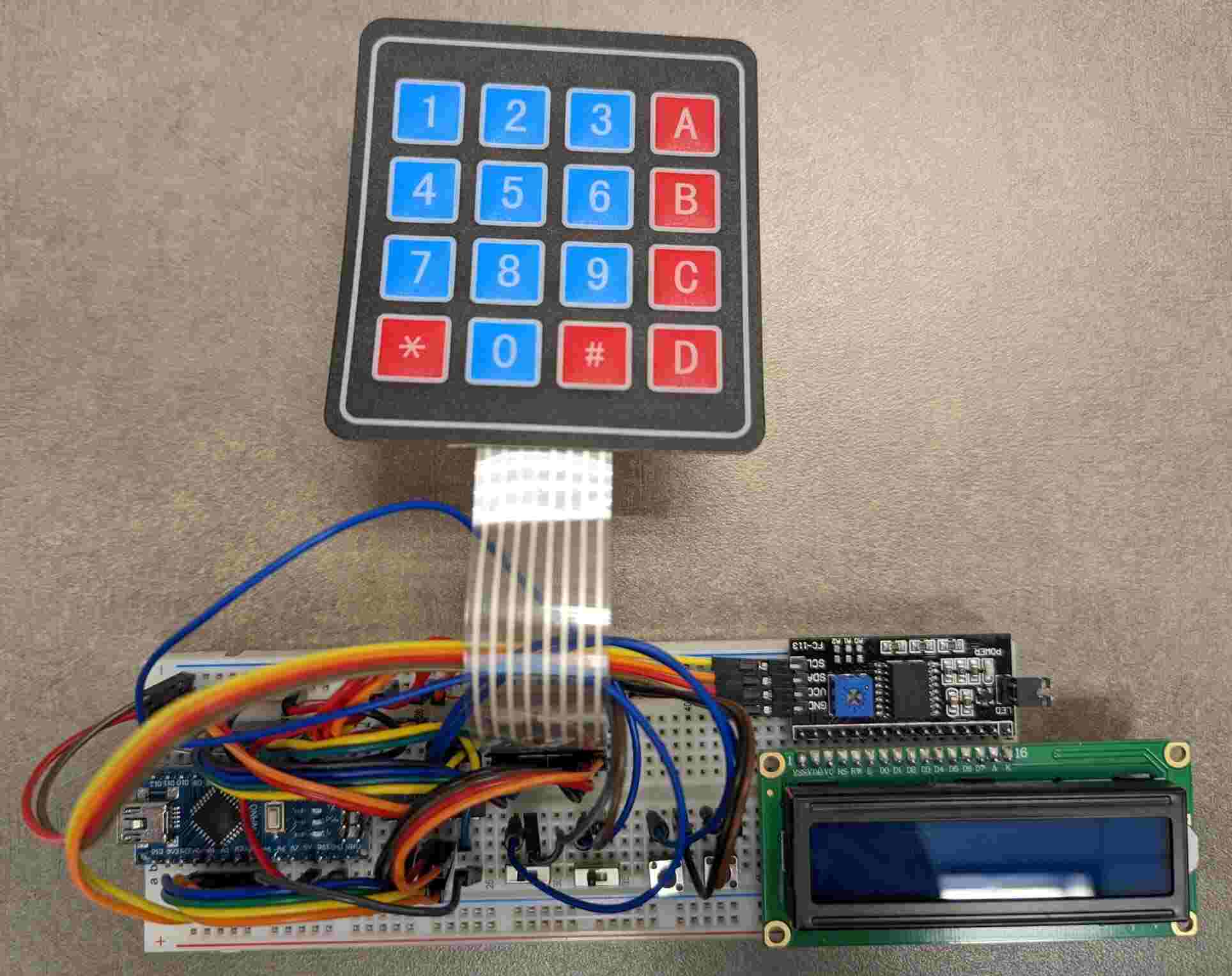
Cow Pi mk1d that was constructed using 10cm and 20cm jumper wires.
Note
In many of the photographs on the following pages, jumper wires from earlier steps have been replaced with cut-to-length wires to emphasize the wires from the current step. This may cause the photographs to look “cleaner” than your circuit.